

Klockner Moeller EASY 512 Programming Instructions
Klockner Moeller EASY 512 & 719 PLCs
Programming Tutorial
Programming the Klockner Moeller EASY mini-PLC
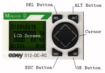 |
This is a front view of the Moeller EASY programmable controller. There are 4 pushbuttons, DEL, ALT, ESC and OK, which are used to program and operate the unit. The large round cursor disk is used to move around menus or circuit diagrams and is operated by pressing near the top, bottom right or left edge. The OK button is used to select menu functions highlighted by the cursor. |
|
See our PLCs catalog. Click here for: technical specifications. Click here for our related downloads.
Click here to Email the Author
See our main page for Klockner Moeller and Siemens parts
|
Table of Contents:
|
The Programming Screens |
|
 |
Status Screen: this shows the condition of the inputs (I) and the outputs (Q). In this case, inputs 3 & 5 are activated and output relay 2 is closed. "RUN" indicates the unit is currently running the program. On models that have the clock, the "WE" on the right indicates "wednesday" and below that is the time of day in 24 hour format. Press the OK button, for the Main Menu. |
 |
Main Menu: You may move up and down using the cursor arrows on the large disk, your present selection is blinking. Selecting "PROGRAM" takes you to the program menu. "RUN" is the start button to begin processing, and means the unit is currently in stop mode. If you see a "STOP" button, the unit is in run mode, and pressing it will stop processing. "PARAMETER" is used to set-up various counters, timers, etc. On models with the clock, you will also have the "SET CLOCK" option. Use the OK button to make your selection. |
 |
Program Menu: To begin programming or to view the circuit diagram, select PROGRAM and press the OK button. Or, to delete your existing program, select "DELETE PROG" and press the OK button. |
 |
Circuit Diagram: This screen begins as a blank, and you type in your desired program. This simple program has only one function: If input 1 (I1) is activated then output relay 1 (Q1) is activated. After you have entered your program, simply hit the ESC button until the Main Menu appears, then select RUN and hit OK. |
Basic Programming |
|
|
|
Circuit Diagram: Power the unit up, then press the OK button 3 times and you will arrive at the blank screen where you will enter your program. We will now write a simple program, which will activate output Q1 when input I1 OR I2 are activated, and will activate output Q2 when both inputs I1 AND I2 are activated. |
 |
Begin with the blank screen and your blinking cursor is in the upper left corner. Note that the screen is 4 columns wide, which allows for 3 contacts plus one coil on the right. Press OK, and I1 will appear, indicating Input 1. Now use the cursor arrow to move all the way to the right and press OK again and the symbol {Q1 will appear, indicating Output 1. |
 |
Now use the cursor disk to move to the left, to the 2nd position, right next to the I1 symbol. Press the ALT button and the line drawing tool appears. Use the cursor again to move the line drawing tool to the right, twice. Now press the ALT button again, to turn the line drawing tool off. The input I1 and the output relay Q1 are now "wired" together. |
 |
Now use the cursor to move to the 2nd row, all the way to the left. Here, press the OK button, and I1 appears. But we wanted I2 here, so use the cursor to move one character to the right, to the "1". Here use the up cursor to change the "1" to a "2" and you will have "I2". Press OK to select it. You are now at the 2nd column so press ALT for the line drawing tool, and "wire" input 2 as shown, then press ALT again to turn the line tool off. |
 |
Now move down to the 3rd line, and press OK twice to enter I1. Note you may use the same input symbol repeatedly. In the next column you press OK and I1 appears, pressing OK again moves you to the "1" of the "I1" and use the UP cursor to change it to "I2" and press OK to select it. Notice the "wires" appear automatically. Move to the far right column and press OK and {Q1 appears, which you will change to {Q2. |
|
|
Fill in any missing "wires" and you're done! Press ESC a few times to reach the Main Menu, and select RUN and press OK and your program is running. |
 |
Programming Parameters: Here is a program using a timer. Timers need parameters set for on-delay or off-delay, time, etc. Enter the symbols shown at left. When you put in the TT1 timer coil, a {Q1 will appear, use the UP cursor to change it to TT1. When you enter the T1 contact, an I1 will appear, again use the UP cursor to change it to T1, and when you press OK to select it, the parameter display will appear. Note, timers are set-up at the contact, not at the coil. |
 |
Parameter Display: Shown here is a typical parameter display. In the case of a timer, the top left symbol indicates type (on-delay, off-delay, etc), in this case the X means "on-delay". Below that the "S" indicates "seconds". The number at the top (01.14) is the actual time that has elapsed and the number below it (07.00) is the preset time. You can move around the parameter display using only the right and left cursor. Use the up and down cursors to change individual values. More specific information appears in the next section below. |
 |
Illegal: If you have more than 4 symbols to place on one line, you could do it the way shown, but THIS WON'T WORK! "Power" flows only to the right. Instead, use 3 symbols and a "marker relay" coil, then place a contact from the marker relay at the beginning of the next line, then continue on. See the section on "marker relays" for the correct method. |
Available Functions |
|
 |
Negation: Relay circuits often require "closed contacts" and this is done with negation. Simply move to any contact on your diagramm and press OK to select it. Then press ALT, and a small line will appear above the symbol. This is now a "normally closed" contact. This works for any type of contact, timers, counters, clocks, etc. In the picture here the output relay Q1 will be energized whenever input I1 is NOT activated. And output relay Q2 will be energized whenever On-Delay Timer T1 is not yet timed out. |
 |
Output Relays: A "normal" output relay is shown here as {Q1. Output Q1 is energized when I1 is activated, and drops out if I1 is deactivated. Latching output relay: remains energized indefinitely once it has been "set", until it is "reset". Two separate coils are used. I2 operates the "set" coil and latches the Q2 in. I3 operates the "reset" coil and causes Q2 to drop out. Impulse or Alternating Relay: This is shown as To create these, move to the right column, and press OK to create a normal {Q1 output relay. Move one digit to the left and use the UP cursor to change to one of the other types. Caution: any relay coil may appear only once in a circuit diagram. |
 |
Output Relay (Q) Contacts: Q-Relays have auxiliary contacts which can be used in any of the 3 left columns. In this example, I1 runs Q1 and I2 runs Q2, but neither of the outputs will activate if the other is already activated. This has an application in a reversing contactor for example. |
 |
Marker Relays: These are handy internal relays which can be used as memory or to extend a row if more than 3 contacts are needed such as in the ILLEGAL example shown at the left. The lower picture shows the correct method, using marker relay M1. Note that marker relays can be of various types: Normal, Latching, Impulse/Alternating, similar to the Q types shown above. |
  |
Counter Relays: These are used to count pulses, usually from inputs. A total is kept, visible on the parameter screen, and when a preset total is reached, the counter's contacts will switch over. Counters can count in either direction, plus or minus. Shown here in the circuit diagram, I1 pulses the CC1 counter coil and the count is incremented by 1 for each pulse. If I2 activates the direction coil DC1, then pulses from I1 will count down I3 can be used to reset the counter back to zero. As the preset amount is reached, contact C1 activates output relay Q1 On the parameter display, the left number (9999) is the preset amount, and the right number (1234) is the running total. The maximum preset is 9999, and maximum count is 9999. The operating speed of the counters is dependant on the complexity of the program. With a simple program they can count up to 100 pulses per second (100 Hz). |
 |
Timers: Shown here is a simple on-delay timer circuit and parameter display. Input I1 activates the TT1 timer "trigger" coil, and the time count begins. Input I2 activates the "reset" timer coil which will rest the time count back down to zero, if desired. When the preset time is elapsed, then timer contact T1 will activate output relay Q1 The "X" in the upper-left corner of the parameter display indicates the type of timer, in this case "on-delay". The "S" indicates the time-units, in this case "Seconds". The number at the top (01.14) indicates the timer has been running 1.14 seconds, and the number below it (07.00) is the preset time. When the preset time is reached then the timer switches. Here are the various types of timers with their parameter symbols: On-Delay, "X,": When the TT1 "trigger" coil is activated, the time count begins and the timer's contacts close when the preset time is reached and then remain closed until power is removed from the trigger coil TT1. A momentary activation of the reset coil RT1 will stop the timer dead and the elapsed time will remain at zero. After the reset coil RT1 is deactivated, the timer remains dead until the trigger coil TT1 is momentarily deactivated and then reactivated.
Off-Delay, "
Single-Pulse, "
Flasher, " Random On-Delay, "?X": This is identical to the normal on-delay "X" function except that the time will be a random number between zero and the preset time.
Random Off-Delay, "? |
   |
Clock Controllers " In this circuit diagram Clock 1 contact " Note there are 2 parameter screens shown, though 4 are possible. You tell them apart by the A, B, C or D near the lower right corner. Those 4 letters are known as "channels". In this case, Channel A turns clock " Another application might be to control lights in a home while the owner is away on vacation. Combined with the "Random On-Delay" and "Random Off-Delay" timers shown in the previous section, the lights will come on not at the exact same times each day but rather at somewhat variable times, thereby more closely simulating an occupied house. |
   |
Analog Comparators: The DC models are able to accept 2 analog 0-10 volt sensors. These are always connected to inputs I7 and I8. Analog Comparator Relays are available to process the information. The circuit diagram in Figure 21 shows comparator A1 will "set" output relay Q1, and comparator A2 will "reset" Q1. The contacts can be used like any other contact, however if the input voltage fluctuates slightly, it may be good to use latch relays so as to prevent chattering. There are 6 specific analog comparators to work with: I7 >= I8: This comparator activates when the voltage on I7 is greater than or equal to the voltage on I8. This is shown in Fig.22, where I7 is 8.4 volts and I8 is 6.1 volts, therefore the condition is met and comparator A1 is activated. Note the 2 numerical displays show the actual voltages present at the 2 inputs. I7 <= I8: This comparator activates when the voltage on I7 is less than or equal to the voltage on I8. I7 >= setpoint: This comparator is activated when the voltage on I7 is greater than or equal to a setpoint value. This is shown in Fig.23, where I7 is presently 8.4 volts and the setpoint is 9.3 volts, therefore the condition is not met and comparator A2 is not activated. I7 <= setpoint: This comparator is activated when the voltage on I7 is less than or equal to a setpoint value. I8 >= setpoint: This comparator is activated when the voltage on I8 is greater than or equal to a setpoint value. I8 <= setpoint: This comparator is activated when the voltage on I8 is less than or equal to a setpoint value.
|
  |
P-Buttons: The 4 cursor buttons can be used as inputs. Here in Fig.24, the left cursor button P1 controls output relay {Q1. The left cursor "<" is P1 The up cursor "^" is P2 The right cursor ">" is P3 The down cursor "v" is P4. To use these P-Buttons, one must enter the system menu and use the "P ON" selection. Fig.25 shows a "P" in the upper right corner, indicating that the P-Buttons are activated. See the section on System Menu, below. |
 |
"if" Jumps: The 700 series units have the ability to "jump" to another section of the program, thereby skipping certain portions. Here in Fig.26, if I1 is not activated, then I2 would control output Q1. But, if I1 were activated, then Jump relay 1 (:1) would activate and the entire second line containing I2 would be skipped and the program would continue at the :1 "contact" marker. In all cases, I3 would still control output Q3. |
 |
Text-Display Variables: The 700 series units are able to display text on the screen as desired, however this can only be entered via EASY-SOFT. Up to 8 Text Variables ( D1 thru D8 ) can be defined, each of up to 12 characters. 4 lines can be displayed at any given time. The text display in Fig.26 shows 4 text variables telling the operator how many pieces have been produced and how many are required for the job's completion, and the running condition of the machine. Permissible displays include actual text as well as variables such as actual values and setpoints of timers, counters, and the time of day. Voltages from analog inputs I7 and I8 can be displayed as actual voltage or as a scaled number representing their function. A text will be displayed whenever that Text Variable ( D1 thru D8 ) is activated. |
System Settings |
|
 |
The System Screen: This is used to set system defaults and startup behavior. To reach this screen, go to the status display by pressing ESC several times, then press DEL and ALT at the same time. Note: This screen is not available if a password is set and "active", you must enter the password first and deactivate it. See below... |
  |
Password Protection: Setting a system password will prevent tampering with the program in the field and will prevent viewing of the program by unauthorized persons. To set a password, enter the System Menu, select "PASSWORD", then select "CHANGE PW" and then enter a 4 digit number for your password. Then press"OK" and you may select "ACTIVATE". If the password appears as "----" then no password is stored. If the password appears as "XXXX" then a previous password had been set and is stored in memory. The password may be any number from 0001 thru 9999. Setting a password of 0000 will completely delete a previous password. If a password is set but not activated, then the password is stored in memory but is not used. If a password is set, you cannot view the program. Use the Program menu selection from the Main Menu to enter your password. An active password prevents: Figure 31 shows a typical parameter screen, in this case a timer. Note the "+" in the lower right corner. This means that the parameter screen for this particular timer is available even when a password is active, and one may change the time values but not the function or type. If a "-" is shown instead of a "+" then the parameters are not viewable or changeable at all. If a machine operator might need to change a parameter but you wish to prevent accidental changes, then set the parameter displays to "+" and activate a password. If you forget your password, there is no "back door" into the unit: Enter an incorrect password 3 times, and the program will be deleted and the password removed and you may then put in a new program. |
|
|
Setting the Menu Language: The various menus can be displayed in any of these languages: English, German, French, Spanish or Italian. The 700 series units also have these additional languages: Portuguese, Dutch, Swedish, Polish and Turkish. On the System Menu, select "GB D F E I" and then select the language desired: |
 |
Debounce: Inputs are sometimes subject to "contact bounce" from pushbuttons or other input devices, which may cause a momentary "chatter" in some circuits. Setting the Debounce will cause an input to delay activation until a "steady" signal is received. This delay is approximately 20 milliseconds. To activate this feature, enter the System Menu, then select "SYSTEM" and the screen shown in Figure 33 will appear. Press "DEBOUNCE ON" to activate. |
|
|
Activating P-Buttons: The cursor arrow buttons on the unit can be programmed into the circuit for use as inputs, but they must be activated before their function will be available. To activate this feature, enter the System Menu, then select "SYSTEM" and the screen shown in Figure 34 will appear. Press "P ON" to activate. |
|
|
Startup Mode: The unit can be set to begin running immediately upon power-up, or alternatively to power-up in the "stop" mode, requiring a manual start from the Main Menu. To activate this feature, enter the System Menu, then select "SYSTEM" and the screen shown in Figure 35 will appear. Press "MODE: RUN" to set the unit to start the program running immediately on power-up, or press "MODE: STOP" to set the program to NOT start on power-up. The default is "RUN" and the programmer will likely want to connect a start button to an input to start the machine actually running. |
|
|
Retention: The units can be set to "retain" or "remember" the value of various functions thru a power-down and resume running exactly where they left off when powered-up again. To activate this feature, enter the System Menu, then select "SYSTEM" and the screen shown in Figure 36 will appear. Press "RETENTION ON" to enable this feature. EASY 512-DC units can remember Marker Relays M13, M14, M15, M16, Timer T8 and Counter C8. EASY 512-AC models do NOT offer this feature. All 700 series units can remember Marker Relays M13, M14, M15, M16, Timer T7, T8 and Counters C5, C6, C7 and C8 and all 8 Text Relays This feature is useful where a machine must remember it's exact place in a continuing process |
Memory Modules (Cards) |
|
  |
Notes: A small memory "Card" is available which is used to store the program much in the way one would use a Floppy Disk. The 512 units use the EASY-M-8K and the 700 series units use the EASY-M-16K Memory Card. This card is a small memory chip that plugs into a little door on the lower right face of the unit, just above the output relay terminals. The Card may be plugged in when the unit is powered up. The unit must be powered up to use it's functions. The unit will automatically detect the presence of a Card, and the Program Menu will then have an additional choice: CARD. This is shown in Figure 40. Select CARD and press OK and you will see the Card Menu. The Card Menu shown in Figure 41 has 3 options: Units that lack the buttons and LCD Screen will automatically load the program from the card to the unit each time the unit is powered up. The Memory Card provides a convenient way to update a program and send the Card to an untrained person in the field for installation. This way the programmer need not travel to the job-site to make program changes. The Memory Card is also a convenient way to archive a copy of the program in case of damage to the unit. |
Expansion Units |
|
  |
Expansion Units: If the requirements exceed the 12 inputs and 6 outputs of the 700 series units, it is possible to select a Master and a Slave unit and connect them together, thereby making available 24 inputs and 12 outputs. The Master and Slave units can be located side-by-side or remote from each other: Side-By-Side Connection: Figure 39 shows a Master unit and a Slave unit mounted side by side, connected by a small plug-connector that is included with the Slave unit. Remote Connection: Figure 40 shows a Master unit and a Remote Connection Unit (EASY-200-EASY) mounted side-by-side, connected by the included plug-connector. The Remote Connection Unit has terminals to connect wires to the remotely located Slave unit. The connection is made with 2 wires or a single twisted-pair and may have a maximum length of 30 meters, approximately 100 feet. In cases where severe interference is present, a shielded 2-wire cable should be used. Note: Only models specifically designated as Master or Slave can be used for expansion. |
Physical Wiring |
|
 |
Connecting DC Inputs: Figure 41 shows the connection for the incoming 24 Volt DC power and the DC operated Inputs. Shown is a pushbutton on Input I2 and a limit switch on Input I4. Wiring for 700 Series DC units is identical. All Inputs (including I7 & I8) are activated when a +24V signal appears on the connection terminal. Inputs I7 and I8 can also be activated by a variable voltage signal up to +10V DC if they are set up as "analog". Also note that the 700 Series units with 12 inputs also use I7 and I8 as their analog inputs. |
 |
Connecting AC Inputs: Figure 42 shows the connection for the incoming Line and Neutral power at 120-240 Volts AC and the AC operated Inputs. Shown is a pushbutton on Input I2 and a limit switch on Input I4. Wiring for 700 Series DC units is identical. AC units do not offer analog inputs. |
 |
Connecting Relay Outputs: Figure 43 shows Relay Output Q2 connected to Load 1 and Relay Output Q3 connected to Load 2. Note that the power (shown as L & N) to the relay outputs can be any voltage up to 250 Volts AC or DC, and they need not all be from the same source. you may mix L1, L2 and L3. The Loads may be relay coils, small motors, lights, etc. |
 |
Connecting Transistor Outputs: Figure 44 shows the 24 Volt DC power connections for the outputs, and shows Transistor Output 2 (Q2) connected to Load 1, and Transistor Output 3 (Q3) connected to Load 2. The loads must all be 24 Volt DC operated, and you must observe polarity. Wiring for 700 Series units with transistor outputs are identical. |
|
A note on AC Inductive Proximity Switches: Certain "inexpensive" proximity switches need to be connected to a load at all times for them to function properly. This load serves to drain the charge from the sensor when it wants to indicate the "low" state. This type of sensor may have difficulty indicating its state to the EASY units, because the EASY units have an extremely small current draw. Depending on the proximity switch, there are 3 possible solutions: 1) Use input 7 or 8, they draw a greater current and this may suffice. 2) Use a "pulldown" resistor of approximately 2k ohms and 5 watts, on any input. Connect this resistor between the EASY's input terminal and the N (neutral) terminal. 3) Use the Moeller EASY256-HCI accessory which provides an appropriate resistor/capacitor combination which increases the input current. Each EASY256-HCI unit will correct a total of 6 input circuits. | |
Specifications |
|
Supply Voltage
|
|
Klockner Moeller Electric & Siemens Sirius - Price Catalog
Klockner Moeller / Moeller Electric - photos
Moeller Electric - xStart - photos
Siemens Relays & Switches - photos
Siemens Sirius - photos
Terms & Conditions